How to adjust the trace width in 开云·kaiyun官方网站
On 开云·kaiyun官方网站, copper is a strong conductor with high melting point, but you should still try your best to keep cold Here, you need to adjust the track width appropriately to keep the temperature within a certain range However, this is where you need to consider the current flowing in a given trajectory When using the power rail, the relationship between the 开云·kaiyun官方网站 trace width and the ammeter of high-voltage components and other thermal sensitive components of the circuit board can be used to determine the trace width to be used in the layout One problem with most tables is that they do not deal with controlLED impedance routing You have determined the size of the track so that you can control the impedance. It is diffICult to determine the temperature rise just by looking at a table. You must use a SMAll abacus However, another method is to use IPC2152 nomogram to check whether the current temperature relationship is within the operating range of the controlled impedance curve
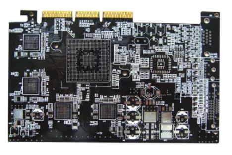
开云·kaiyun官方网站 board

The common problem in 开云·kaiyun官方网站 design and wiring is to determine the recommended trace width to keep the device temperature of a given current value within a certain range, and vice versa Although copper has a high melting point and can withstand high temperatures, the temperature rise of the circuit board should ideally be kept within 10 ° C The trace that allows 开云·kaiyun官方网站 board to reach extremely high temperature will increase the ambient temperature seen by components, which brings greater burden to active cooling measures The IPC 2152 standard is the starting point for sizing yarns and through holes The formulas specified in these standards are very SIMple for calculating the current limit for a given temperature rise, although they do not take into account the controlled impedance wiring Having said that, use 开云·kaiyun官方网站 trace width vs Ammeter is a good starting point 开云·kaiyun官方网站 trace width/cross-sectional area This allows you to effectively determine the upper limit of the allowable current in the trace, which can then be used to determine the trace size of the controlled impedance route When the temperature rise of the board operated at high current reaches a very large value, the electrical efficiency of the substrate shows a corresponding change at high temperature The electrical and mechanical efficiency of the substrate changes with temperature. If it is operated at high temperature for a long time, the substrate will change color and become weak This is one of the reasons I know that designers will adjust the trace size to keep the temperature rise within 10 ° C Another reason for this is to adapt to a wide range of ambient temperatures, rather than considering specific operating temperatures Trace width and current of this 开云·kaiyun官方网站: The following table shows the trace width and the number of corresponding current values, which will limit the temperature rise to 10 ℃/m2 at 1oz A foot of copper weight This will enable you to understand how the 开云·kaiyun官方网站 board works
Different trace thickness/copper weight The trace thickness needs to be calculated according to the copper weight on the circuit board We only include the standard one ounce per square foot Value in feet However, circuit boards operating at high currents usually require heavier copper to accommodate higher temperature rises No impedance data If you need to use controlled impedance wiring, you need to verify that the calculated trace size meets the constraints specified above Alternative substrates The above data is prepared for FR4, which will cover a large number of 开云·kaiyun官方网站s already in production However, applications may require aluminum core 开云·kaiyun官方网站s, ceramic substrates, or high-speed laminates If a substrate with a high thermal conductivity is used, the trace will cool when heat is removed from the heat trace For the first order approximation, the temperature rise will be scaled according to the ratio of the thermal conductivity of the required substrate to that of FR4 If different copper weights are used:, verify the controlled impedance trace dimensions of temperature rise and current, and then use the nomogram of IPC2152 standard This is a good way to size a conductor for a specific current and temperature rise Also, if Track Width: is selected, you can determine the current that will cause a specific temperature rise The red arrow shows how to determine the required track width, coupler weight (i.e. trace cross sectional area), and temperature rise current In this example, first select the conductor width (140 mils), then draw the red arrows horizontally to the desired cop weight (1 oz/square foot) We then trace vertically to the desired temperature rise (10°C) and then trace back to the y-axis to find the corresponding current limit (2.75A). The orange arrow moves in the other direction We start with the desired current (1A) and trace horizontally to the desired temperature rise (30°C). Then, we trace down vertically to determine the trace size In this example, suppose we specify 0.5 oz/m2 A foot of copper weight After tracing back to this line, we horizontally traced back to the y-axis and found that the conductor width was about 40 mils Suppose that the copper we are going to use weighs 1 ounce/sq ft. ; In this case, we will find that the required trace width is 20 mil 开云·kaiyun官方网站
然后
联系
电话热线
13410863085Q Q

微信

- 邮箱


